



















WinCounter Wiring Diagrams
WinCounter requires a sensor or switch connected to the serial port (com port) of your computer. A basic connection only requires a single switch contact and a resistor. We can supply connecting cables and interfaces. You can wire your own connector or have a local electrician/alarm installer etc. wire a cable and sensor for you.
The basic requirement for triggering WinCounter is to switch DSR from DTR to RTS. The simplest way is to connect a switch is to use single switch contact between DSR and RTS and a pull-up resistor between DSR and DTR. The wiring diagrams for this configuration are shown below. It doesn't matter if your sensor contact is normally open or normally closed as you can adjust WinCounter to trigger from the appropriate switch action. You can also configure it to trigger from a leading or trailing edge in the software.
WinCounter requires a loopback connection on the data lines of the serial port to help determine if a WinCounter cable is connected to the serial port.
This diagram below shows a simplified wring concept for connection to a sensor or switch. We recommend using additional components to filter and/or optically isolate the sensor or switch from the computer serial port.
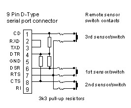
Wiring for up to 3 sensors on a 9 pin serial port.
If you are not using the additional sensors still connect the pull-up resistors.